Setting up a 2*node windows 2016 on-prem fileserver cluster and 1*Windows 2016 fileserver on Azure
In previous posts (part1 and part2) of this series I discussed about the overall solution and how to configure on-prem and cloud StorSimple storage systems. I also explained the steps to provision the storage to servers from StorSimple storage.
The focus of this post is to discuss about the requirements and steps to create an on-prem Scale-Out-Fileserver cluster and a standalone fileserver on Azure for DR capability. I would highly recommend considering having a good read of the requirements and good practices to plan and design your fileserver cluster:
Plan for Storage in Scale-Out File Server
Plan for Networking in Scale-Out File Server
So once the storage has been provisioned from StorSimple to all the 3 servers (2 for on-prem cluster and 1 for azure fileserver), we need to mount the volumes to servers and do some configuration magic to create a highly available fileserver environment.
As suggested in my previous blog, for the high availability of your StorSimple solution, it’s a good idea configuring MPIO on file server cluster (optional) prior to configuring iSCSI. MPIO configuration on host servers will ensure that the servers can tolerate a link, network, or interface failure.
Step 1: Install MPIO on the Windows Server host
- Open Server Manager on your Windows Server host. By default, Server Manager starts when a member of the Administrators group logs on to a computer that is running Windows Server 2012 R2 or Windows Server 2012. If the Server Manager is not already open, click Start > Server Manager.
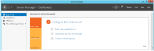
- Click Server Manager > Dashboard > Add roles and features. This starts the Add Roles and Features wizard.
- In the Add Roles and Features wizard, perform the following steps:
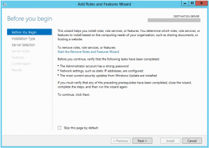
- On the Before you begin page, click Next.
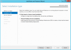
- On the Select installation type page, accept the default setting of Role-based or feature-based installation. Click Next.
- On the Select destination server page, choose Select a server from the server pool. Your host server should be discovered automatically. Click Next.
- On the Select server roles page, click Next.
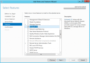
- On the Select features page, select Multipath I/O, and click Next.
- On the Confirm installation selections page, confirm the selection, and then select Restart the destination server automatically if required, as shown below. Click Install.
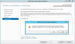
- You are notified when the installation is complete. Click Close to close the wizard.
Step 2: Configure MPIO for StorSimple volumes
- Open the MPIO configuration. Click Server Manager > Dashboard > Tools > MPIO.
- In the MPIO Properties dialog box, select the Discover Multi-Paths tab.
- Select Add support for iSCSI devices, and then click Add.
- Reboot the server when prompted.
- In the MPIO Properties dialog box, click the MPIO Devices tab. Click Add.
- In the Add MPIO Support dialog box, under Device Hardware ID, enter your device serial number. To get the device serial number, access your StorSimple Device Manager service. Navigate to Devices > Dashboard. The device serial number is displayed in the right Quick Glance pane of the device dashboard.
- Reboot the server when prompted.
Step 3: Mount StorSimple volumes on the host
After MPIO is configured on Windows Server, volume(s) created on the StorSimple device can be mounted and can then take advantage of MPIO for redundancy. To mount a volume, perform the following steps.
- Open the iSCSI Initiator Properties window on the Windows Server host. Click Server Manager > Dashboard > Tools > iSCSI Initiator.
- In the iSCSI Initiator Properties dialog box, click the Discovery tab, and then click Discover Target Portal.
- In the Discover Target Portal dialog box, perform the following steps:
- Enter the IP address of the DATA port of your StorSimple device (for example, enter DATA 0).
- Click OK to return to the iSCSI Initiator Properties dialog box.
Note: If you are using a private network for iSCSI connections, enter the IP address of the DATA port that is connected to the private network.
- Repeat steps 2-3 for a second network interface (for example, DATA 1) on your device. Keep in mind that these interfaces should be enabled for iSCSI.
- Select the Targets tab in the iSCSI Initiator Properties dialog box. You should see the StorSimple device target IQN under Discovered Targets.
- Click Connect to establish an iSCSI session with your StorSimple device. A Connect to Target dialog box appears.
- In the Connect to Target dialog box, select the Enable multi-path check box. Click Advanced.
- In the Advanced Settings dialog box, perform the following steps:
- On the Local Adapter drop-down list, select Microsoft iSCSI Initiator.
- On the Initiator IP drop-down list, select the IP address of the host.
- On the Target Portal IP drop-down list, select the IP of device interface.
- Click OK to return to the iSCSI Initiator Properties dialog box.
- Click Properties. In the Properties dialog box, click Add Session.
- In the Connect to Target dialog box, select the Enable multi-path check box. Click Advanced.
- In the Advanced Settings dialog box:
- On the Local adapter drop-down list, select Microsoft iSCSI Initiator.
- On the Initiator IP drop-down list, select the IP address corresponding to the host. In this case, you are connecting two network interfaces on the device to a single network interface on the host. Therefore, this interface is the same as that provided for the first session.
- On the Target Portal IP drop-down list, select the IP address for the second data interface enabled on the device.
- Click OK to return to the iSCSI Initiator Properties dialog box. You have added a second session to the target.
- Open Computer Management by navigating to Server Manager > Dashboard > Computer Management. In the left pane, click Storage > Disk Management. The volume created on the StorSimple device that are visible to this host appears under Disk Management as new disk(s).
- Initialize the disk and create a new volume. During the format process, select a block size of 64 KB.
- Under Disk Management, right-click the Disk and select Properties.
- In the StorSimple Model #### Multi-Path Disk Device Properties dialog box, click the MPIO tab.
- In the DSM Name section, click Details and verify that the parameters are set to the default parameters. The default parameters are:
- Path Verify Period = 30
- Retry Count = 3
- PDO Remove Period = 20
- Retry Interval = 1
- Path Verify Enabled = Unchecked.
Note: Do not modify the default parameters.
Step 4: Configure MPIO for high availability and load balancing
For multi-path based high availability and load balancing, multiple sessions must be manually added to declare the different paths available.
- Perform a discovery of the target: in the iSCSI Initiator Properties dialog box, on the Discovery tab, click Discover Portal.
- In the Connect to Target dialog box, enter the IP address of one of the device network interfaces.
- Click OK to return to the iSCSI Initiator Properties dialog box.
- In the iSCSI Initiator Properties dialog box, select the Targets tab, highlight the discovered target, and then click Connect. The Connect to Target dialog box appears.
- In the Connect to Target dialog box:
- Leave the default selected target setting for Add this connection to the list of favorite targets. This makes the device automatically attempt to restart the connection every time this computer restarts.
- Select the Enable multi-path check box.
- Click Advanced.
- In the Advanced Settings dialog box:
- On the Local Adapter drop-down list, select Microsoft iSCSI Initiator.
- On the Initiator IP drop-down list, select the IP address corresponding to the first interface on the host (iSCSI interface).
- On the Target Portal IP drop-down list, select the IP address for the first data interface enabled on the device.
- Click OK to return to the iSCSI Initiator Properties dialog box.
- Click Properties, and in the Properties dialog box, click Add Session.
- In the Connect to Target dialog box, select the Enable multi-path check box, and then click Advanced.
- In the Advanced Settings dialog box:
- On the Local adapter drop-down list, select Microsoft iSCSI Initiator.
- On the Initiator IP drop-down list, select the IP address corresponding to the second iSCSI interface on the host.
- On the Target Portal IP drop-down list, select the IP address for the second data interface enabled on the device.
- Click OK to return to the iSCSI Initiator Properties dialog box. You have now added a second session to the target.
- Repeat Steps 8-10 to add additional sessions (paths) to the target. With two interfaces on the host and two on the device, you can add a total of four sessions.
- After adding the desired sessions (paths), in the iSCSI Initiator Properties dialog box, select the target and click Properties. On the Sessions tab of the Properties dialog box, note the four session identifiers that correspond to the possible path permutations. To cancel a session, select the check box next to a session identifier, and then click Disconnect.
- To view devices presented within sessions, select the Devices tab. To configure the MPIO policy for a selected device, click MPIO. The Device Details dialog box appears. On the MPIO tab, you can select the appropriate Load Balance Policy settings. You can also view the Active or Standby path type.
Deploying on-prem fileserver cluster
XXX-FLS-001 and XXX-FLS-002 will be cluster members for XXX-CLU-001. Before the cluster can be created, a validation check should be performed to make sure the configuration is as per the requirement.
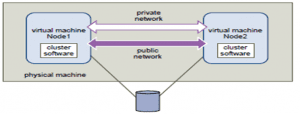
FileServer Cluster Representation
Install role services and features
- Log on to the server as a member of the local Administrators group.
- Server Manager will start automatically. If it does not automatically start, click Start, and then click Server Manager.
- In the QUICK START section, click Add roles and features.
- On the Before you begin page of the Add Roles and Features Wizard, click Next.
- On the Select installation type page, click Role-based or feature-based installation, and then click Next.
- On the Select destination server page, select the appropriate server, and then click Next. The local server is selected by default.
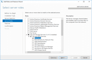
- On the Select server roles page, expand File and Storage Services, expand File Services, and then select the File Server check box. Click Next.
- On the Select features page, select the Failover Clustering check box, and then click Next.
- On the Confirm installation selections page, click Install.
- Repeat the steps in this procedure for each server that will be added to the cluster.
The Cluster service controls server cluster operations and manages the cluster database. A cluster is a collection of independent computers that act as a single computer. Managers, programmers, and users see the cluster as a single system. The software distributes data among the nodes of the cluster. If a node fails, other nodes provide the services and data that were formerly provided by the missing node. When a node is added or repaired, the cluster software migrates some data to that node.
Make sure this service is running on all the nodes that are planned to part of the cluster.
System service name: ClusSvc
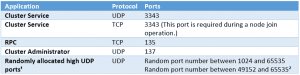
Note: Additionally, for successful validation on Windows Failover Clusters on 2008 and above, allow inbound and outbound traffic for ICMP4, ICMP6, and port 445/TCP for SMB.
Validate hardware and create a cluster
- Log on to the server as a member of the local Administrators group.
- Server Manager will start automatically. If it does not automatically start, click Start, and then click Server Manager.
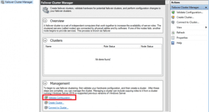
- Click Tools, and then click Failover Cluster Manager.
- Under the Management heading, click Validate Configuration.
- On the Before You Begin page, click Next.
- On the Select Servers or a Cluster page, in the Enter name box, type the FQDN of one of the servers that will be part of the cluster, and then click Add. Repeat this step for each server that will be in the cluster.
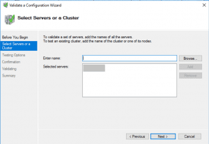
- Click Next.
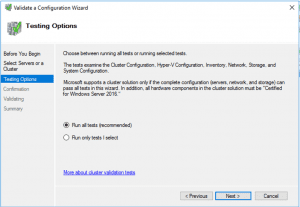
- On the Testing Options page, ensure that the Run all tests (recommended) option is selected, and then click Next.
- On the Confirmation page, click Next.
- On the Summary page, ensure that the Create the cluster now using the validated nodes check box is selected, and then click Finish. The Create Cluster Wizard appears.
- On the Before You Begin page, click Next.
- On the Access Point for Administering the Cluster page, in the Cluster Name box, type a name for the cluster, and then click Next.
- On the Confirmation page, click Next.
- On the Summary page, click Finish.
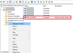
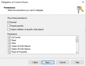
Giving Cluster computer account rights to create computer object:
If we don’t delegate rights to Cluster computer object, we won’t be able to add cluster File Server role
- Right click OU where Cluster Computer object is created-Delegate control
- Object Types-Computer
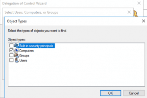
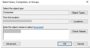
- Create custom task to delegate
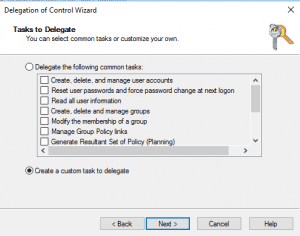
- Only the following objects in the folder-Computer Object-Create selected objects in this folder
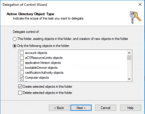
- General-Full Control
Add storage to a cluster shared volume
A cluster shared volume is used by a failover cluster, and it can be accessed by more than one node at a time.
- Log on to the server as a member of the local Administrators group.
- Server Manager will start automatically. If it does not automatically start, click Start, and then click Server Manager.
- Click Tools, and then click Failover Cluster Manager.
- Click Storage, right-click the disk that you want to add to the cluster shared volume, and then click Add to Cluster Shared Volumes.
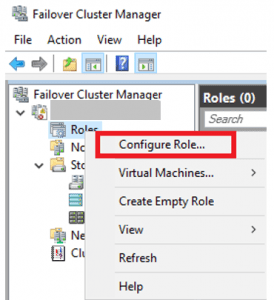
Configure Scale-Out File Server
- Sign in to the server as a member of the local Administrators group.
- To open Failover Cluster Manager in Server Manager, click Tools, and then click Failover Cluster Manager.
- Right-click the name of the cluster, and then click Configure Role.
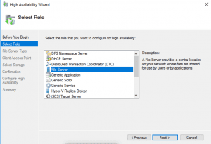
- On the Before You Begin page, click Next.
- On the Select Role page, click File Server, and then click Next.
- On the File Server Type page, select the Scale-Out File Server for application data option, and then click Next.
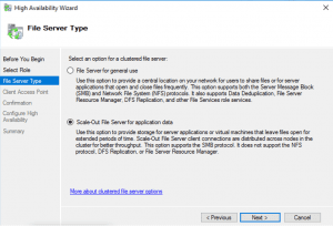
- On the Client Access Point page, in the Name box, type a NETBIOS name that will be used to access Scale-Out File Server, and then click Next.
- On the Confirmation page, confirm your settings, and then click Next.
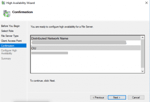
- On the Summary page, click Finish.
Create a continuously available file share on the cluster shared volume
- Sign in to the server as a member of the local Administrators group.
- To open Failover Cluster Manager in Server Manager, click Tools, and then click Failover Cluster Manager.
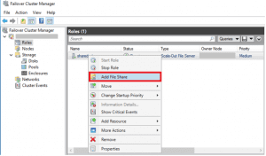
- Expand the cluster, and then click Roles.
- Right-click the file server role, and then click Add File Share.
- On the Select the profile for this share page, click SMB Share – Applications, and then click Next.
- On the Select the server and path for this share page, click the name of the cluster shared volume, and then click Next.
- On the Specify share name page, in the Share name box, type a name for the file share, and then click Next.
- On the Configure share settings page, ensure that the Enable continuous availability check box is selected, and then click Next.
- On the Specify permissions to control access page, click Customize permissions, grant the following permissions, and then click Next:
- If you are using this Scale-Out File Server file share for Hyper-V: All Hyper-V computer accounts, the SYSTEM account, cluster computer account for any Hyper-V clusters, and all Hyper-V administrators must be granted full control on the share and the file system.
- If you are using Scale-Out File Server on Microsoft SQL Server: The SQL Server service account must be granted full control on the share and the file system.
- On the Confirm selections page, click Create.
- On the View results page, click Close.
Create a new fileserver Azure for DR failover
XXX-FLS-003 will serve as a standalone fileserver in azure in case a DR event occurs. So, the only steps that need to be performed on this server are:
- Install MPIO on the Windows Server host
- Configure MPIO for StorSimple volumes
- Mount StorSimple volumes on the host
- Configure MPIO for high availability and load balancing
- Install role services and features
Once these steps are complete, just create smb file shares to replicate the shares from on-prem fileservers. I’ll discuss more about this in the next and last part of the series.
Other parts of the series are as below:
Part 1: Introduction to solution, Microsoft StorSimple device and Windows 2016 file server cluster
Part 2: Setting up the on-prem StorSimple 8600 device and StorSimple 8020 cloud appliance
Part 4: Failover to cloud appliance in case of DR event